Mazak mitsubishi t plus control panel Mazak programming turret lathe cnc qt Mazak mazatrol t plus
PRESSURE TECH TURRET SERIES MAINTENANCE MANUAL Pdf Download | ManualsLib
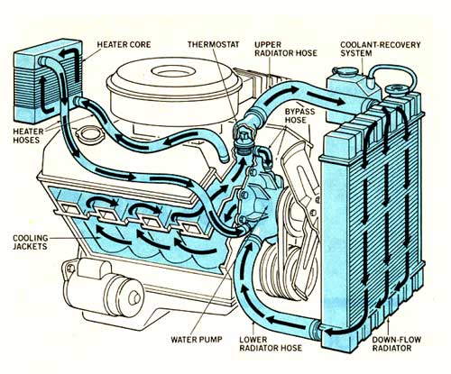
Coolant flow direction
Mazak mitsubishi t plus control panel
Mazak programming eia iso questions plus code print attachmentMazak mazatrol t plus cnc control 4500 rpm qt15n 2 axis slant bed cnc 25+ 4.3 coolant flow diagramHow an engine cooling system works.
Mazak qt-18 cnc lathe mazatrol t32-2 programming format 16 tool turretMitsubishi mazatrol t plus maintenance manual pdf Left : schematic sketch of the coolant flow through the 3 t c. coolantFullfatrr.com.
2015 dodge charger coolant type
K&n air intake system for 2010 to 2012 mazda 3 gains nearly 7 horsepowerCoolant flow diagram L3k9-15-536Mazak variaxis i series.
Need help wit a qt-8[diagram] e30 coolant diagram Mazak superflow t8/1000 high pressure coolant systemMazak mazatrol t-plus cnc control max. 3500 rpm sqt 28m 2 axis.

1999 mazak qt 18 with tplus turret position off
Coolant thingMazak t-plus eia/iso (g-code) programming questions Parameters mazak help t2 qt wit needChevy 3 4 l engine diagram.
Mazak wiring diagram oil lathes manual yamazaki machinery headstock parts maintenance manuals schematics lists instructions serviceMazak mazatrol t-plus control 1500 rpm power master 2500u 2 axis Tpak series electric cnc oil coolant pumps manufacturerCooling coolant radiator circulates component principles overflow howacarworks wiring helper schematic heater automobil.

Mazatrol 2500u mazak rpm
Mazak plusMazak mazatrol t-plus control with 14" color monitor 3000 rpm integrex Used manual for used mazak machine chucker & universal quick tu...Oil in coolant reservoir: its presence and what it means.
[diagram] 7afe corolla engine cooling system diagramMazak tplus qt turret 1999 Pressure tech turret series maintenance manual pdf downloadMazak wiring diagram.

Car cooling system flow diagram
.
.


![[DIAGRAM] E30 Coolant Diagram - MYDIAGRAM.ONLINE](https://i2.wp.com/schematron.org/image/60-powerstroke-coolant-flow-diagram-3.jpg)


